Category Archives: Security

IPsec made simple

Understanding IP security protocol (IPsec) terminology and principles can be a hard task due to the wide range of documentation. This tutorial facilitates this task by providing a succinct documentation and a chronological description of the main steps needed to establish an IPsec tunnel.

Get started

IPsec is a set of protocols developed by the IETF to support secure exchange of packets at the IP layer. IPsec includes protocols for establishing mutual authentication between peers at the beginning of the session and negotiation of cryptographic keys to be used during the session. IPsec is available for both IPv4 and IPv6 and has been deployed widely to implement Virtual Private Networks (VPNs). This tutorial covers IKEv1 and IPv4 only.

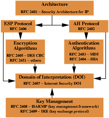
Interrelationship of IPsec core documents is illustrated in the following schema:

The Architecture document covers the general concepts, security requirements, definitions, and mechanisms defining IPsec technology.

The ESP Protocol and AH Protocol documents cover the packet format and general issues regarding the respective protocols.

The Encryption Algorithms document is the set of documents describing how various encryption algorithms are used for ESP.

The Authentication Algorithm is the set of documents describing how various authentication algorithms are used for both ESP and AH.

The DOI document contains values needed for the other documents to relate to each other. This includes for example encryption algorithms, authentication algorithms, and operational parameters.

The Key Management Documents are the documents describing the IETF standards-track key management schemes (ISAKMP/Oakley, IKE).

How IPsec works

An IPsec tunnel establishment process can be broken down into five main steps: tunnel initiation, IKE Phase 1, IKE Phase 2, data transfer and tunnel termination.

Tunnel initiation: IPsec tunnel initiation can be triggered manually or automatically when network traffic is flagged for protection according to the IPsec security policy configured in the IPsec peers. In both cases, the Internet Key Exchange Protocol (IKE) process starts.

IKE Phase 1, IKE Phase 2: IKE offers a means to automatically negotiate security parameters and derive suitable keying material. IKE also manages the process of re-creating, or refreshing, frequently keys to ensure data confidentiality between peers. The basic operation of IKE can be broken down into two phases: IKE phase 1 and IKE phase 2.

IKE phase 1: This phase is used to negotiate the parameters and key material required to establish an ISAKMP Security Association (ISAKMP SA). The ISAKMP SA is then used to protect future IKE exchanges and to set up a secure channel for negotiating IPsec SAs in IKE phase 2.

IKE Phase 2: This phase is used to negotiate the parameters and key material required to establish two unidirectional IPsec SAs for incoming and outgoing traffic. The IPSEC SAs are then used to protect network traffic during Data transfer phase.

Data transfer: Incoming and outgoing network traffic is encapsulated according to the bundle of algorithms and parameters provided by their respective negotiated IPsec SA to provide confidentiality and authenticity (ESP protocol) or authenticity only (AH protocol).

Tunnel termination: A tunnel is closed when its IPsec SAs terminate through deletion or by timing out. An IPsec SA can time out when a specified number of seconds have elapsed or when a specified number of bytes have passed through the tunnel.

IKE Phase 1

IKE phase 1’s purpose is to establish a secure authenticated communication channel by using the Diffie–Hellman key exchange algorithm to generate a shared secret key to encrypt further IKE communications. This negotiation results in one single bi-directional ISAKMP SA. The authentication can be performed using either pre-shared key (shared secret), digital signatures, or public key encryption as described by RFC 2409.

IKE Phase 1 operates in either Main Mode or Aggressive Mode. Main Mode protects the identity of the peers but Aggressive Mode does not.

Main Mode has three two-way exchanges between the initiator and the receiver.

    • First exchange: The algorithms and hashes used to secure the IKE communications are agreed upon in matching ISAKMP SAs in each peer.
    • Second exchange: Uses a Diffie-Hellman exchange to generate shared secret keying material used to generate shared secret keys and to pass nonces numbers sent to the other party and then signed and returned to prove their identity.
    • Third exchange: Verifies the other side’s identity (the identity value is an IP address, an FQDN, an email address, a DNS or a KEY ID form in encrypted form). The main outcome of main mode is matching ISAKMP SAs between peers to provide a protected pipe for subsequent protected ISAKMP exchanges between the IKE peers. The ISAKMP SA specifies values for the IKE exchange: the authentication method used, the encryption and hash algorithms, the Diffie-Hellman group used, the lifetime of the ISAKMP SA in seconds or kilobytes, and the shared secret key values for the encryption algorithms. The ISAKMP SA in each peer is bi-directional.

Aggressive Mode has fewer exchanges with fewer packets. On the first exchange, almost everything is squeezed into the proposed ISAKMP SA values: the Diffie-Hellman public key (a nonce that the other party signs) and an identity packet, which can be used to verify identity via a third party. The receiver sends everything back that is needed to complete the exchange. The only thing left is for the initiator to confirm the exchange. The weakness of using the aggressive mode is that both sides have exchanged information before there’s a secure channel. Therefore, it’s possible to sniff the wire and discover who formed the new SA. However, it is faster than main mode.

NAT Traversal also known as UDP encapsulation is a general term for techniques that establish and maintain Internet protocol connections traversing network address translation (NAT) gateways and devices. RFC 3947 defines the negotiation during the Internet key exchange (IKE) phase and RFC 3948 defines the UDP encapsulation.

Dead Peer Detection (DPD) is used to monitor the peer and quickly detect when it gets unreachable. It works by exchanging probe packets, and if the peer does not answer for some time, the security associations are killed. DPD is documented by RFC 3706.

XAUTH, Mode config and Hybrid authentication are optional extensions of the IKE phase 1 described in RFC drafts.

Extended Authentication (XAUTH) provides additional user authentication by prompting the user for a username and password.

Mode config is used to deliver parameters such as IP address and DNS address to the client.

Hybrid authentication makes the IKE phase 1 asymmetric: the VPN IPsec server authenticates to the IPsec clients by using a certificate, and the client does not authenticate in IKE phase 1. This extension is usually used with XAUTH to provide a high security level.

IKE Phase 2

The purpose of IKE phase 2 is to negotiate IPsec SAs to set up the IPsec tunnel. IKE phase 2 performs the following functions:

    • Negotiates IPsec SA parameters protected by an existing ISAKMP SA.
    • Establishes IPsec security associations.
    • Periodically renegotiates IPsec SAs to ensure security.
    • Optionally performs an additional Diffie-Hellman exchange.

IKE phase 2 has one mode called quick mode. Quick mode occurs after IKE has established the secure tunnel in IKE phase 1. It negotiates a shared IPsec policy, derives shared secret keying material used for the IPsec security algorithms, and establishes IPsec SAs. Quick mode exchanges nonces that provide replay protection. The nonces are used to generate new shared secret key material and prevent replay attacks from generating bogus SAs.

Quick mode is also used to renegotiate a new IPsec SA when the IPsec SA lifetime expires. Base quick mode is used to refresh the keying material used to create the shared secret key based on the keying material derived from the Diffie-Hellman exchange in IKE phase 1.

If perfect forward secrecy (PFS) is specified in the IPsec policy, a new Diffie-Hellman exchange is performed with each quick mode, providing keying material that has greater entropy (key material life) and thereby greater resistance to cryptographic attacks. Each Diffie-Hellman exchange requires large exponentiations, thereby increasing CPU use and exacting a performance cost.

When the IPsec SAs terminate, the keys are also discarded. When subsequent IPsec SAs are needed for a flow, IKE performs a new IKE phase 2 and, if necessary, a new IKE phase 1 negotiation. A successful negotiation results in new IPsec SAs and new keys. New IPsec SAs can be established before the existing SAs expire, so that a given flow can continue uninterrupted.

Data transfer

IPsec protocols are AH (Authentication Header) and ESP (Encapsulating Security Payloads):
AH is a format protocol defined in RFC 2402 that provides data authentication, integrity, and non repudiation but does not provide data confidentiality. This protocol has largely been superseded by ESP.
ESP is a format protocol defined in RFC 2406 that provides data confidentiality, integrity and data origin authentication, replay attack protection.
ESP supports the use of symmetric encryption algorithms, including DES, 3DES, and AES, for confidentiality and the use of MD5 HMAC and SHA1 HMAC for data authentication and integrity.

AH and ESP protocols support two modes of use: Transport and Tunnel.
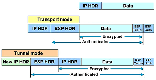
Transport mode encrypts only the data portion of each packet, but leaves the header untouched. Tunnel mode is more secure and encrypts both the header and the payload.

The figures below describe the most common ways to encapsulate original IP packets:

Tunnel/Transport modes using AH protocol

 Tunnel/Transport modes using ESP protocol
Wi-Fi Protected Setup (WPS)

Many home users leave their Wi-Fi networks partially or completely unsecured because they possess little understanding of traditional Wi-Fi configuration and security settings including what a SSID is and the difference between WEP, WPA, and WPA2 and their associated ciphers.
The Wi-Fi Protected Setup (WPS) standard is introduced to facilitate the deployment of secure Wi-Fi networks without any complicated procedures and the insertion of additional devices over time.

Recently, an important security vulnerability was discovered in the current WPS Registration Protocol specification and implementations putting Wi-Fi networks at risk. The exploit is explained in the WPS vulnerability section.

This tutorial also provides a general overview of the WPS technology.

WPS methods

Wi-Fi Protected Setup (WPS), developed by the Wi-Fi Alliance, helps users quickly and easily configure WPA/WPA2-Personal (PSK) security on wireless routers and clients. WPS currently supports two methods: Personal Information Number (PIN) and Push Button Configuration (PBC). The specification also includes a third method, Near-Field Communication (NFC) but there are currently no products that support NFC.

The PIN method allows users to use a PIN (taken either from a sticker label or a utility screen or a web-based control panel) and enter it in the Access Point (AP) or client WPS device to connect. This method is mandatory for all WPS certified devices.

The push button configuration (PBC) method allows users to simply push a button, either an actual or a virtual one, on both WPS devices to connect. This is an optional method on wireless clients.

In both methods, WPS users are not asked to enter a network name (SSID) and wireless security by hand. The whole operation often takes few seconds and it does not exceed a two-minute period.

WPS Components

There are three logical components involved in WPS:

    • Registrar: a device with the authority to issue and revoke credentials to a network. A registrar may be integrated into a wireless access point (AP), or it may be separate from the AP.
    • Enrollee: a device seeking to join an access point or a wireless network such as a laptop, a cell phone …
    • AP: an Access Point functioning as a proxy between a registrar and an enrollee.


Interface E is logically located between the Enrollee and the Registrar (physically, the AP can work as a proxy to convey the messages). The purpose of Interface E is to enable the Registrar to discover and issue WLAN Credentials to the Enrollee.

Interface M is the interface between the AP and the Registrar. It enables an external Registrar to manage a WPS AP. WPS uses the same protocol for setting up the AP Management interface as for issuing Credentials to Enrollee devices.

Interface A is between the Enrollee and the AP. The function of Interface A is to enable discovery of the WPS WLAN and to enable communication between the Enrollee and IP-only Registrars.

Registration Protocol

The Registration Protocol is defined and detailed in the Wi-Fi Protected Setup Specification v1.0 document provided by the Wi-Fi Alliance. The Registration Protocol accomplishes the following purposes:

    • It helps to troubleshoot basic connectivity problems with the wireless channel.
    • It provides demonstrative identification of the Enrollee to the Registrar and the Registrar to the Enrollee using out-of-band information, enabling the credential configuration function.
    • It establishes the roles of each device (AP, Registrar, or Enrollee).
    • It securely conveys WLAN settings and other configuration from the Registrar to the Enrollee.
    • It establishes an Extended Master Session Key EMSK, which can be used to secure additional application-specific configuration functions.

The Registration Protocol is used for a variety of scenarios resulting in a few variants in terms of optional parameters. The principal version, a series of EAP message exchanges, is described as below:

Enrollee -> Registrar: M1 = Version || N1 || Description || PKE
Enrollee <- Registrar: M2 = Version || N1 || N2 || Description || PKR [ || ConfigData ] || HMAC_AuthKey(M1 || M2*)
Enrollee -> Registrar: M3 = Version || N2 || E-Hash1 || E-Hash2 || HMAC_AuthKey(M2 || M3*)
Enrollee <- Registrar: M4 = Version || N1 || R-Hash1 || R-Hash2 || ENC_KeyWrapKey(R-S1) || HMAC_AuthKey (M3 || M4*)
Enrollee -> Registrar: M5 = Version || N2 || ENC_KeyWrapKey(E-S1) || HMAC_AuthKey (M4 || M5*)
Enrollee <- Registrar: M6 = Version || N1 || ENC_KeyWrapKey(R-S2) || HMAC_AuthKey (M5 || M6*)
Enrollee -> Registrar: M7 = Version || N2 || ENC_KeyWrapKey(E-S2 [||ConfigData]) || HMAC_AuthKey (M6 || M7*)
Enrollee <- Registrar: M8 = Version || N1 || [ ENC_KeyWrapKey(ConfigData) ] || HMAC_AuthKey (M7 || M8*)

• || this symbol means concatenation of parameters to form a message.
• Mn* is message Mn excluding the HMAC-SHA-256 value.
• Version identifies the type of Registration Protocol message.
• N1 is a 128-bit random number (nonce) specified by the Enrollee.
• N2 is a 128-bit random number (nonce) specified by the Registrar.
• Description contains a human-readable description of the sending device (UUID, manufacturer, model number, MAC address, etc.) and device capabilities such as supported algorithms, I/O channels, Registration Protocol role, etc. Description data is also included in 802.11 probe request and probe response messages.
• HMAC_AuthKey(…) This notation indicates an Authenticator attribute that contains a HMAC keyed hash over the values in parentheses and using the key AuthKey. The keyed hash function is HMAC-SHA-256 per FIPS 180-2 and RFC-2104. To reduce message sizes, only 64 bits of the 256-bit HMAC output are included in the Authenticator attribute.
• ENC_KeyWrapKey(…) This notation indicates symmetric encryption of the values in parentheses
using the key KeyWrapKey. The encryption algorithm is AES-CBC per FIPS 197, with PKCS#5 v2.0 padding.
• PKE and PKR are Diffie-Hellman public keys of the Enrollee and Registrar, respectively. If support for other cipher suites (such as elliptic curve) is added in the future, a different protocol
Version number will be used.
• AuthKey is an authentication key derived from the Diffie-Hellman secret, the nonces N1 and N2, and the Enrollee’s MAC address. If M1 and M2 are both transported over a channel that is not susceptible to man-in-the-middle attack, the Enrollee’s device password may be omitted from the key derivation.
• E-Hash1 and E-Hash2 are pre-commitments made by the Enrollee to prove knowledge of the two halves of its own device password.
• R-Hash1 and R-Hash2 are pre-commitments made by the Registrar to prove knowledge of the two halves of the Enrollee’s device password.
• R-S1 and R-S2 are secret 128-bit nonces that, together with R-Hash1 and R-Hash2, can be used by the Enrollee to confirm the Registrar’s knowledge of the first and second half of the Enrollee’s device password, respectively.
• E-S1 and E-S2 are secret 128-bit nonces that, together with E-Hash1 and E-Hash2, can be used by the Registrar to confirm the Enrollee’s knowledge of the first and second half of the Enrollee’s device password, respectively.
• ConfigData contains WLAN settings and Credentials for the Enrollee. Additional settings for other networks and applications may also be included in ConfigData. Although ConfigData is shown here as always being encrypted, encryption is only mandatory for keys and key bindings. Encryption is optional for other configuration data. It is the sender’s decision whether or not to encrypt a given part of the ConfigData.

WPS vulnerability

The PIN method (mandatory for certification) requires only the knowledge of the PIN making the WPS potentially vulnerable to brute force attacks. Discovering the PIN exposes the WPA/WPA2 PSK found in ConfigData which contains the WLAN settings and Credentials for the Enrollee.

Basically, these attacks rely on discovering the PIN much quicker than brute forcing the PSK and work as follow:

    • If the WPS Registration Protocol fails at some point, the Registrar will send a NACK message.
    • If the attacker receives a NACK message after sending M4, he knows that the first half of the PIN was incorrect. See definition of R-Hash1 and R-Hash2.
    • If the attacker receives a NACK message after sending M6, he knows that the second half of the PIN was incorrect.

This method dramatically decreases the maximum possible authentication attempts needed from 10^8 to 10^4 + 10^4. The 8th digit of the PIN is always a checksum of digit one to digit seven. As result, there are at most 10^4 + 10^3 (=11.000) attempts needed to find the correct PIN.
Consequently, less than four hours are needed to allow an attacker to try all possible PIN combinations with a reasonable 1.3 seconds per attempt.

An attack tool called Reaver  has been released to get WPS enabled devices PIN, and has been tested against a wide variety of WPS implementations.

As nearly all major router and access point vendors have WPS certified devices, a lot of devices are vulnerable to this kind of attack. WPS is often enabled by default and implemented without any kind of blocking mechanism to prevent brute force attacks making this vulnerability even worse.

Since this vulnerability can only be patched with a firmware update, it is recommended to apply one of the following solutions:

    • If allowed by your WPS device, disable the WPS feature using your WEB management interface then configure your wireless connectivity manually.
    • Check your WPS device vendor’s support website for updated firmware that addresses this vulnerability.

Network traffic filtering technologies for Windows

Network traffic Filtering techniques for Windows, either in user-mode or kernel-mode, falls into one of two categories: stream and packet methods. This document presents useful techniques to build robust security software products such as personal firewalls and VPN clients for Windows 2000 or higher.

Before going further with this article, I would personally recommend WPF for Vista and higher, and TDI filters + NDIS Hook for earlier versions to build a combined stream and packet filtering solutions.

Winsock Layered Service Provider

A Winsock Layered Service Provider (LSP) is a DLL that operates on the Winsock functions to inspect, modify and intercept the inbound and outbound Internet traffic as streams and not as packets. LSP also runs in the workspace of the process it intercepts making easy to filter streams based on caller PID, short name or full path.

LSP can be chained and are useful tool for data-monitoring, content filtering, stream based sniffers, Quality of Service (QoS), authentication, encryption … LSP technology is often exploited by spyware and adware programs to bombard users with advertisements and email spam.

There is one known limitation and one common issue with LSPs. On some Windows versions, LSP can be bypassed by calling TCP/IP stack directly via TDI making useless, for instance, Trojan or virus protections at this level. A bogus LSP or improper LSP removal/unregistration operation may break the whole TCP/IP stack or leave the machine without working network connection.

Windows 2000/XP Filter Hook Driver

A Filter Hook driver is supported on Windows 2000/XP only and is implemented as a kernel mode driver. It operates by registering a callback with the IP Filter Driver that gets called when sending a receiving a packet. Filtering rules are limited to pass, drop or forward decision based on IP addresses and ports information.

The callback registration process uses an IRP with IOCTL_PF_SET_EXTENSION_POINTER as an IO control code and a PF_SET_EXTENSION_HOOK_INFO structure filled with a pointer to the callback routine.

A Filter Hook driver is simple to implement but has three serious limitations. Only one callback routine can be installed each time on the system. It is not possible to filter Ethernet frames. Outgoing packets cannot be modified.

Windows 2000/XP Firewall Hook Driver

A Firewall Hook driver is very similar to a Filter-Hook driver but installs a callback in the IP driver. The callback registration process uses an IRP with IOCTL_IP_SET_FIREWALL_HOOK as an IO control code and an IP_SET_FIREWALL_HOOK_INFO structure filled with a pointer to the callback routine.

Although it is not well documented, writing a Firewall Hook driver requires few lines of code. The main limitation is the support of Windows 2000 and XP only.

NDIS Hook Driver

There are two approved techniques to write an NDIS Hook driver. The first one is based on interception of some NDIS wrapper functions at runtime by writing a kernel mode driver that patches NDIS.sys in memory to replace the addresses of NdisRegisterProtocol, NdisDeregisterProtocol, NdisOpenAdapter and NdisCloseAdapter functions with internal ones.

The second one is based on registering a fake NDIS Protocol driver just to get a pointer to an internal NDIS structure NDIS_PROTOCOL_BLOCK.

At this level, both methods have enough information to substitute all protocols and adapters handlers to getting full control over all network traffic.

Although these approaches use sophisticated hacking techniques and require good understanding of different NDIS versions internals, an NDIS Hook driver is easy to install and able to filter, inject or modify packets. Several security software products including personal firewalls and VPN clients use these techniques.

This approach is discouraged for Windows Vista and higher.

NDIS Intermediate Driver

An NDIS intermediate driver, also called NDIS IM driver, is inserted just above miniport drivers and just below transport protocols in the overall networking protocol stack allowing incoming and outgoing packets filtering, inspection or modification. An NDIS Intermediate driver is a documented alternative to NDIS Hook drivers and offers the same functionalities.

NDIS intermediate drivers should be digitally signed at Microsoft to allow silent installations. This technology is replaced by NDIS Lightweight Filter drivers on Vista and higher.

NDIS Lightweight Filter Driver

NDIS Lightweight Filter drivers (LWF drivers) are introduced in Windows Vista and higher to replace NDIS Intermediate driver technology. They offer the same packets filtering, inspection or modification capabilities.

NDIS Lightweight Filter drivers are easier to implement and are designed to improve overall performances.

TDI Filter Driver

The Transport Driver Interface (TDI) defines a kernel mode network interface that is exposed at the upper edge of all transport protocol stacks. TDI also provides standard methods for protocol addressing, sending and receiving datagrams, writing and reading streams, initiating connections, detecting disconnects making it the only socket interface in the kernel.

TDI Filter drivers sit between TDI clients (such as AFD.sys, NETBT.sys) and TDI transports (such as TCPIP.sys) and intercept the communication between them. In case of TCP/IP filtering, the technique consists in writing a kernel-mode driver that layers itself over devices created by TCPIP.sys driver (\Device\RawIp, \Device\Udp, \Device\Tcp, \Device\Ip and \Device\MULTICAST) using IoAttachDevice routine. A good understanding of how to handle and interact with IRPs is required.

It is recommended to stop using TDI filters and move to Windows Filtering Platform (WFP) on Vista and later platforms. Windows makes it possible for TDI filters to see TCP/IP traffic is just for compatibility reasons and it does not yield good performance.

Windows Filtering Platform

Windows Filtering Platform (WPF) is a new architecture available in Windows Vista and higher that was built to replace all existing packet filtering technologies such as Winsock LSP, TDI filter and NDIS Intermediate driver and to provide better performance and less development complexities. Callout drivers, Filter Engine, Base Filtering Engine and Shims are components of the WPF architecture.

The WFP API consists of a user-mode API and a kernel-mode API that interacts with the packet processing that takes place at several layers in the networking stack. With WFP, incoming and outgoing packets can be filtered and modified before they reach their destinations, making this architecture ideal for implementing various filtering applications or solutions (such as personal firewalls, intrusion detection systems, antivirus programs, network monitoring tools, and parental controls). WFP arbitration rules also minimize the risk that software components get affected by any future Service Pack release.

WPF is highly recommended for developing security related solutions on Vista and higher.